
Quick and dirty 5 minutes craft: Draw a rough shape, define the contact surfaces & load, click run, and get the optimized shape. The last step is converting the output to a printable shape and running one more simulation to double-check it is strong enough.
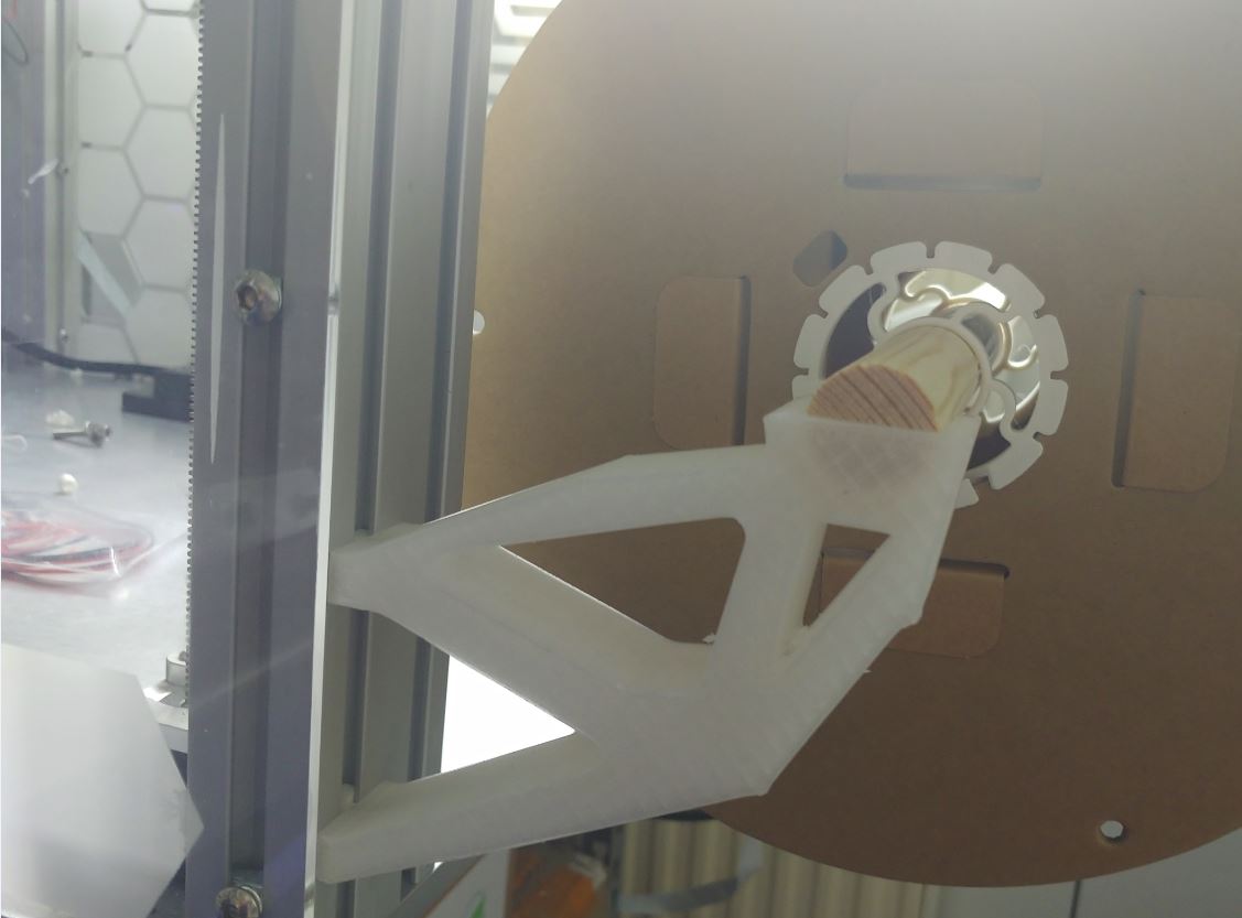
This particular holder is a filament spool holder designed to be loaded with up to 5.5kg of filament (1x2.5kg, 3x1kg).
I take it there’s another holder on the other side.
May I ask why the complex shape, rather than just having a triangle with two points on the 4040 rail and the third point being the axle position?
I imagine the “optimized” there means it has the maximum weight support with the minimum amount of filament.
This shape certainly beats a triangle with only the walls or with just a bit of infill. And it surely takes less filament than one with near to 100% of infill.
I don’t follow you. Look at the photo, the thing is made of triangles. It’s the best shape. So I wonder, why use more than just one? Why make the shape require more than one triangle?
Hum, ok, I misunderstood you.
Your 1 triangle will need the inclination similar to that middle segment of the bottom side of the piece. I will be huge.
More than likely the static supports used in the software were in the locations you see now,1 for spool and other’s bellow on the rail. They said “draw a rough shape” as a step, so that dictated the shape.
If the static loads were placed at even height you would end up more triangle like or more of a truss. Depends shown many iterations were used also.
In a broader picture: See it as a demonstration of what all those nice tools in the CAD package can do. In this application with a little bit of thought could come up with a similar or better solution but for an I don’t care design approach the output is already good. A proper design approach would be putting thought in in where to place the contact surfaces relative to the spool and then run this software or go a step further and allow a different software to also change that parameter. Keep in mind those simulations are computationally expensive. Complex/advanced questions might take days to solve while a simple question like this is less than 1 minute.
The load was in the circle/groove facing down.
The other constrain was the faces contacting the 3030 extrusion being fixed and a keep-out zone was defined around those to ensure no material there was removed.
Otherwise, it was just a flat slab as shape.
What at first surprised me was how this part works: There is a point defined by the lowest/left triangle (tension & compression) on which all the weight rests. The remaining structure is is a cross beam (top mounting point to spool) to support it (tension) and the structure on which the spool rests (compression).
Nature loves triangles.
https://en.wikipedia.org/wiki/Michell_structures
The thing with 3D printing is that it is usually stronger and uses less filament when you do a full shape without holes.
These shapes work well with conventional manufacturing, but 3D printing is different because it is mostly hollow on the inside
Less filament, yes. But it’s almost always weaker.
It’s common to add holes so you get a stronger part.